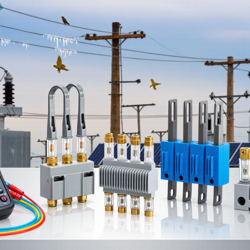
| Expulsion Fuse Cutout | Overhead distribution transformers, lateral feeders, and capacitor banks. | The fuse link melts and the arc is extinguished by gases produced inside the fuse tube, usually causing the tube to drop open. | Commonly up to 27 kV or 38 kV class; current ratings often range from approximately 1 A to 200 A, depending on the assembly. | Visible isolation, simple construction, and convenient field replacement. | Confirm system voltage, interrupting rating, mounting arrangement, phase spacing, terminal orientation, and grounding requirements. | Use the specified fuse-link speed and ampere rating; inspect the tube, hinge, contacts, latch, and insulators for damage or contamination. |
| Open-Link Cutout | Basic overhead feeder and transformer protection where visible fuse status is desirable. | A replaceable fuse link is installed in an exposed or semi-exposed carrier; melting interrupts the fault current and opens the circuit. | Often used on medium-voltage distribution systems; exact voltage and current limits depend on the cutout design. | Low complexity, clear visual indication, and generally straightforward maintenance. | Check required creepage and clearance, environmental exposure, carrier compatibility, and whether the installation location permits this design. | Never substitute a fuse link solely by physical size; verify time-current characteristics and coordination with upstream and downstream protection. |
| Enclosed-Link Cutout | Installations requiring a more protected fuse-link carrier and improved resistance to weather, animals, or accidental contact. | The fuse link is enclosed in a tube or carrier that contains the arc and supports controlled interruption. | Available across several low- and medium-voltage distribution classes; ratings must be matched to the complete assembly. | Improved physical protection and reduced exposure of energized components. | Check enclosure condition, venting requirements, insulation level, mounting hardware, and compatibility with the specified fuse link. | Replace cracked, heat-damaged, carbon-tracked, or moisture-contaminated carriers; confirm the fuse link is seated correctly. |
| Dropout Cutout | Outdoor overhead circuits where an automatic open position provides a visible indication of operation. | After the fuse link operates, the hinged carrier drops away from the upper contact, creating a visible open circuit. | Common in medium-voltage distribution, frequently in 15 kV, 27 kV, and 38 kV classes; exact ratings vary by construction. | Visible fault indication and convenient manual isolation using approved live-line procedures. | Verify operating clearances, mechanical travel, pole and crossarm strength, wind and ice exposure, and accessibility for maintenance. | Check that the carrier drops freely, the latch resets correctly, and the contacts are not burned, loose, misaligned, or excessively worn. |
| Current-Limiting Fuse Cutout | Transformer, feeder, and equipment protection where available fault current may exceed the interrupting capability of an expulsion fuse. | A specially constructed fuse element and filler limit peak fault current and interrupt it within the fuse body. | Often selected for medium-voltage systems with high prospective short-circuit current; the interrupting rating must be confirmed from the product documentation. | High fault-current interruption and reduced let-through energy when properly coordinated. | Compare available fault current, voltage rating, minimum interrupting current, maximum interrupting rating, and coordination curves. | Replace the complete approved fuse unit when required; do not use an expulsion link as a substitute or bypass a failed current-limiting element. |
| Polymer-Insulated Cutout | Outdoor distribution in coastal, polluted, high-humidity, or weight-sensitive locations. | The fuse mechanism operates like the selected fuse type while a polymer housing provides external insulation and weather resistance. | Commonly supplied for medium-voltage distribution classes; electrical ratings depend on the specific design. | Lower weight and good resistance to many environmental conditions when correctly selected. | Check leakage distance, ultraviolet exposure, pollution level, seal condition, mechanical strength, and compatibility with the pole hardware. | Inspect for cuts, punctures, tracking, chalking, loss of hydrophobicity, loose fittings, and evidence of thermal stress. |
| Porcelain-Insulated Cutout | Outdoor distribution systems requiring rigid, established insulation construction and strong resistance to ultraviolet exposure. | The porcelain body provides insulation while the selected fuse carrier and link perform the interruption function. | Available for common low- and medium-voltage distribution applications; confirm the exact insulation and interrupting ratings. | Rigid construction, long service history, and good ultraviolet stability. | Look for chips, cracks, cement deterioration, contamination, correct mounting torque, and adequate phase-to-ground clearance. | Do not reuse cracked or chipped porcelain; inspect metal fittings and verify that replacement parts match the original insulation class. |
| Dual-Element or Time-Delay Fuse Link | Transformer primary protection where temporary magnetizing inrush or permissible overloads should not cause unnecessary operation. | A time-current design tolerates short-duration inrush while operating for sustained overloads or faults within its specified curve. | Ampere ratings are application-specific and must be selected from transformer load, inrush, and coordination calculations. | Can reduce nuisance operations during transformer energization when correctly coordinated. | Review transformer full-load current, inrush duration, secondary protection, available fault current, and the manufacturer’s time-current curve. | Use the same approved speed category and rating unless a protection study authorizes a change; never increase amperage merely to stop repeated blowing. |