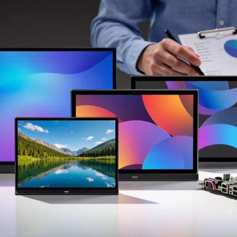
| MIPI TFT display | A TFT LCD module that uses a MIPI display interface, commonly MIPI DSI, to transfer image data and control information between a host processor and the display. | Confirm the module’s interface type, resolution, active area, operating voltage, connector, and compatibility with the intended host. |
| MIPI DSI purpose | MIPI DSI (Display Serial Interface) is a serial interface specification for connecting a host processor to a display module. It defines communication between the host and the display peripheral. | Ask for an interface specification and confirm that the host’s DSI controller and software support the module’s configuration. |
| DSI data transport | DSI carries display data and commands in packets over a serial link. The host sends pixel data for display updates and can also send commands to configure or control the display. | Check the required pixel format, command set, initialization sequence, and any host-side driver or integration documentation. |
| Physical-layer lanes | DSI commonly uses a clock lane and one or more data lanes. The supported lane count and lane speed depend on the host, display module, and physical-layer configuration. | Verify lane count, lane mapping, signal requirements, and maximum supported data rate at both ends; do not assume all DSI devices use the same configuration. |
| Operating modes | DSI supports video-mode and command-mode operation. Video mode streams image data; command mode sends commands and updates display memory as supported by the display. | Confirm which mode the module requires and whether it suits the application’s refresh, power, and software requirements. |
| Bandwidth planning | Required link bandwidth depends on resolution, refresh rate, pixel format, lane count, and protocol overhead. The available bandwidth must be sufficient for the selected display timing. | Request the display timing and link parameters, then validate the complete configuration against the host’s DSI capabilities. |
| Display specifications | Common module specifications include diagonal size, resolution, brightness, viewing angle, color depth, backlight characteristics, and operating temperature range. | Compare documented specifications with the product’s actual optical, mechanical, and environmental requirements; request test reports where applicable. |
| Electrical and mechanical integration | Successful integration also depends on power rails, reset and control signals, connector pinout, flex-cable dimensions, mounting features, and backlight drive requirements. | Review the datasheet, drawings, pinout, power-up sequence, and sample hardware before finalizing the design. |
| Manufacturer capability | Relevant capabilities include display-module design, sourcing or fabrication arrangements, customization, assembly, quality control, and engineering support. | Assess documented process controls, sample consistency, traceability, change management, production capacity, and communication during engineering validation. |
| Quality and reliability | Useful evaluation evidence may include inspection criteria, functional test coverage, environmental test methods, and a defined process for handling nonconforming products. | Request applicable quality documents and test records, and agree on acceptance criteria, inspection methods, and warranty terms before production. |
| How to identify a suitable supplier | There is no single “best” manufacturer for every project: suitability depends on interface compatibility, display performance, customization needs, quality evidence, lead time, and total project cost. | Compare multiple qualified suppliers using the same requirements, sample tests, technical review, and commercial criteria rather than relying on a single ranking. |