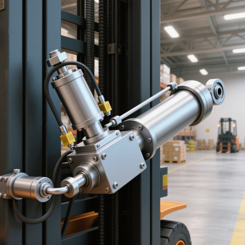
| Fork and mast lift | Hydraulic cylinder system | Raises and lowers the carriage, forks, and load through the mast chain and pulley arrangement. | Cylinder force commonly ranges from approximately 20 to 150 kN, depending on rated capacity and mast design. | About 0.8–6 m cylinder or mast-related travel, depending on lift height and reeving. | Controlled hydraulic lifting; commonly about 0.15–0.60 m/s at the carriage. | Rated load, hydraulic pressure, buckling resistance, rod side-load protection, cushioning, and load-holding performance. | Verify the actuator against the truck’s load chart, maximum lift height, hydraulic pressure, and required lowering speed. |
| Mast tilt | Double-acting hydraulic cylinder | Tilts the mast forward or backward to position the load and improve load stability. | Often approximately 10–60 kN per cylinder, subject to mast geometry and truck capacity. | Typically supports around 5–12° of mast tilt in each direction. | Smooth positioning rather than maximum speed; commonly about 3–10°/s. | High side-load tolerance, precise metering, corrosion resistance, and reliable seals under frequent cycling. | Select cushioning and valve control carefully to prevent abrupt load movement at the end of tilt travel. |
| Fork positioning | Hydraulic cylinder or compact electro-hydraulic actuator | Moves forks inward or outward to accommodate different pallet widths and load shapes. | Commonly approximately 5–25 kN per positioning actuator. | Usually 0.2–1.0 m of fork adjustment, depending on attachment geometry. | Typically about 0.05–0.25 m/s for controlled fork movement. | Synchronized movement, low friction, overload protection, compact envelope, and clear visibility around the attachment. | Check the attachment’s residual capacity because added actuator and attachment weight reduces usable lifting capacity. |
| Side-shift carriage | Short-stroke hydraulic cylinder | Moves the carriage laterally without repositioning the truck. | Usually approximately 8–30 kN, depending on friction, load offset, and attachment design. | Commonly 50–150 mm total lateral travel. | Typically about 0.05–0.20 m/s. | Short retracted length, adequate lateral guidance, pressure protection, and resistance to impact loads. | Confirm that the carriage and cylinder remain within the rated load center and attachment capacity. |
| Attachment rotation | Hydraulic rotary actuator or hydraulic motor with reduction gear | Rotates drums, bins, clamps, or other attachments to orient or discharge a load. | Approximately 1–15 kN·m, depending on load inertia, eccentricity, and attachment size. | Commonly 180–360° rotation; some applications require continuous rotation. | Typically about 2–15 rpm for controlled handling. | Holding torque, braking or counterbalance control, end-stop protection, hose routing, and resistance to shock loading. | Calculate torque from load weight, center of gravity, friction, acceleration, and a suitable safety factor. |
| Clamping attachment | Hydraulic cylinder with pressure-regulated circuit | Applies and releases gripping force around cartons, rolls, appliances, or other loads. | Approximately 5–50 kN per cylinder; required force depends strongly on friction and load surface. | Often 0.1–0.8 m jaw travel. | Typically about 0.03–0.20 m/s to limit product damage. | Accurate pressure control, anti-drop protection, synchronized jaws, cushioning, and suitable contact-pad alignment. | Set grip force from the weakest allowable load condition; excessive force can deform or damage products. |
| Electric auxiliary control | Electromechanical linear actuator | Operates smaller functions such as covers, latches, sensor mounts, access mechanisms, or low-force positioning systems. | Commonly approximately 0.5–8 kN linear force. | Typically 50–500 mm stroke. | Often about 5–50 mm/s, depending on load and duty cycle. | Battery voltage compatibility, current draw, duty cycle, position feedback, mechanical locking, and ingress protection. | Use only where the actuator can fail safely; do not substitute it for a certified load-holding hydraulic system without engineering validation. |
| Operator control linkage | Electrical actuator, solenoid valve, or proportional valve actuator | Converts a lever, switch, joystick, or electronic command into hydraulic flow or mechanical movement. | Small control forces commonly range from approximately 50 N to 2 kN; valve torque is application-specific. | Usually 5–100 mm linear travel or limited rotary movement. | Fast enough for responsive control, commonly about 0.05–0.50 m/s equivalent motion. | Fail-safe behavior, proportional response, electrical noise immunity, connector sealing, and diagnostic feedback. | Prioritize predictable response and fault detection over raw speed; validate compatibility with the truck control system. |