What Are Industrial Valves and How Do They Work?
Industrial valves are the quiet decision-makers inside factories, pipelines, power stations, and water-treatment plants. They start, stop, direct, throttle, or protect fluid movement. A valve may appear simple, yet its failure can halt production, damage equipment, or create serious safety risks. Understanding how industrial valves work begins with their purpose, construction, and operating conditions.
Béla G. Lipták, a respected process-control authority, described the control valve as “the final control element in most process control loops.” That statement explains its importance. Sensors measure pressure, temperature, or flow. A controller processes the signal. The valve then moves, often within seconds, to change the process. Inside a chemical plant, for example, a pneumatic actuator may push a stem downward while a plug narrows the flow passage. Small movements can produce significant changes.
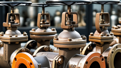
Industrial valves include gate, globe, ball, butterfly, check, and safety valves. Each design suits different pressures, temperatures, fluids, and maintenance demands. A ball valve can isolate a line quickly. A globe valve offers finer regulation. A check valve prevents reverse flow without manual operation. These distinctions matter in real systems, not only in diagrams.
Selection is rarely perfect. Engineers must balance cost, corrosion resistance, pressure drop, leakage control, and service life. A valve that works well with clean water may struggle with abrasive slurry. Installation errors also matter. Even an excellent valve can fail when the actuator is misaligned or the sealing material is unsuitable. This guide examines the main valve types, their working principles, and the practical choices behind reliable industrial service.
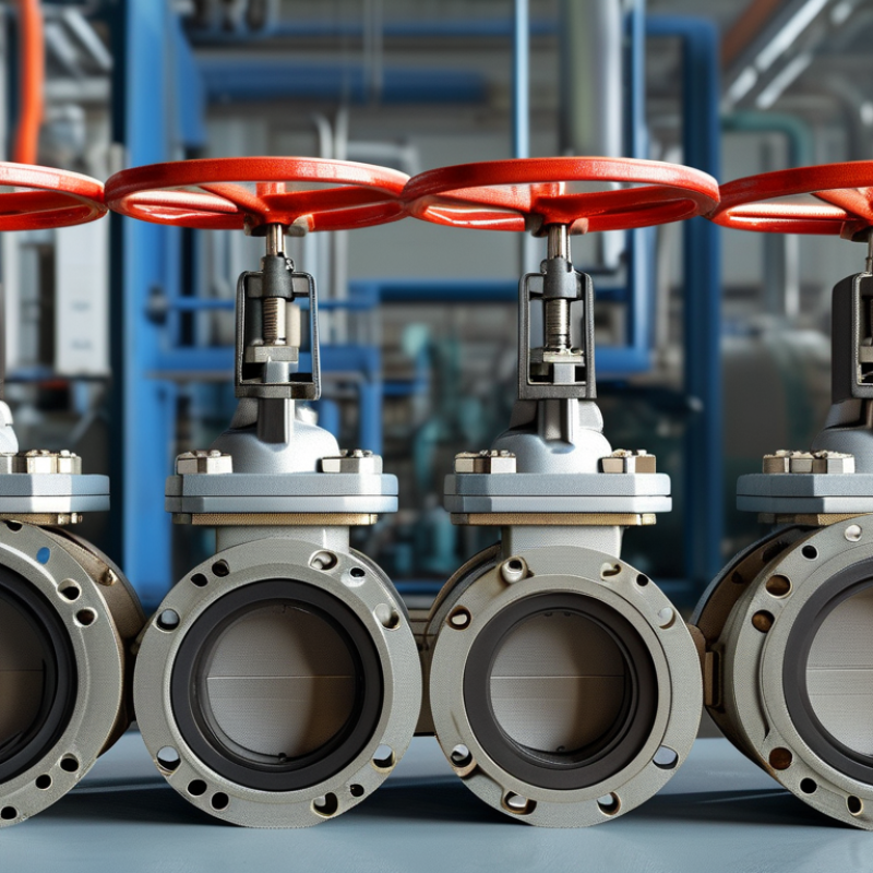
What Industrial Valves Are: Flow-Control Devices in ASME Class 150–2500
Industrial valves are flow-control devices used to start, stop, throttle, or redirect fluids. They operate in pipelines carrying water, steam, chemicals, oil, and gas. Common designs include gate, globe, ball, butterfly, check, and control valves. Each design handles flow differently.
ASME Class 150–2500 describes pressure-temperature ratings, not simple valve size. A Class 150 valve generally supports lower pressure than a Class 2500 valve at the same temperature. Actual limits depend on material, trim, body design, and service conditions.
A gate valve usually provides low resistance when fully open, while a globe valve offers more precise throttling. Check valves use fluid movement to close automatically. Small details matter. A wrong gasket, actuator, or flange rating can cause leakage or premature failure.
Temperature changes also affect pressure limits, so relying only on the class number can be misleading.
Tips: Match the valve to the fluid, temperature, pressure, and required flow control.
Check the full ASME pressure-temperature table before installation.
Inspect seals, bolting, and alignment during maintenance.
A practical field lesson is simple: even a correct specification can fail when installation conditions are overlooked.
Document torque values and test results.
Leave room for reflection, because operating data may reveal that the original valve selection was only partly suitable.
How Valves Control Flow: Pressure Drop, Port Geometry, and Cv Sizing
Industrial valves regulate, isolate, or redirect fluids inside piping systems. Their basic action is simple: a moving element changes the available opening. This change creates resistance and controls flow. Pressure drop is the pressure difference between the valve inlet and outlet. A larger pressure drop usually means stronger throttling, but it can also increase noise, vibration, and energy loss.
Port geometry strongly affects performance. A full-port valve offers a passage close to the pipe diameter, reducing restriction when fully open. A reduced-port design creates more resistance, even at full travel. Globe-style bodies often provide precise throttling, while rotary designs can respond quickly. Cv sizing gives engineers a practical flow estimate. For liquids, the common relationship is Q = Cv × √(ΔP/SG), where Q is flow, ΔP is pressure drop, and SG is specific gravity. Gas sizing requires additional checks for pressure ratio, temperature, and possible choked flow. Do not treat one equation as universal.
Tips: Size for the real operating range, not only the maximum flow. Check minimum flow too. An oversized valve may operate nearly closed, causing unstable control. An undersized valve can waste pressure and accelerate wear. Field measurements matter. Pipe friction, fluid temperature, and changing demand can defeat a clean calculation. I have seen designs look correct on paper but perform poorly after installation. That gap deserves review.
How Industrial Valves Control Flow: Pressure Drop and Cv Sizing
This chart shows the relationship between water flow and pressure drop for valves with different flow coefficients (Cv).
Under standard liquid conditions, flow is estimated by Q = Cv × √(ΔP / SG), where Q is flow in US gallons per minute,
ΔP is pressure drop in psi, and SG is specific gravity. For water, SG is approximately 1. A higher Cv allows more flow at the same pressure drop.
Port geometry, opening position, and internal restrictions determine the effective Cv of a valve.
Industrial Valve Types: Gate, Globe, Ball, Butterfly, and Check Designs
Industrial valves regulate, isolate, or redirect fluids in processing plants, water networks, and power systems. A 2024 market assessment by Grand View Research valued the global industrial valve market at approximately USD 77 billion in 2023. That scale reflects constant demand, but valve selection remains highly practical.
Gate valves provide low resistance when fully open. Their wedge moves vertically, like a door rising from the pipeline. They suit isolation, not frequent throttling. Globe valves control flow more accurately because fluid changes direction inside the body. This creates higher pressure loss. Ball valves use a drilled sphere and usually open with a quarter turn. They shut quickly and seal tightly, although dirty media can damage the seat. Butterfly valves rotate a thin disc around a central shaft. They are lighter and often economical for large pipes, but disc position affects flow. Check valves operate automatically. They stop reverse flow without an operator.
Field experience shows that a correct valve can still fail after poor installation. Pipe strain, incorrect gasket compression, and unfiltered solids are common causes. The U.S. Department of Energy identifies pumping and compressed-fluid systems as major industrial energy users, so unnecessary pressure loss deserves attention. A smaller valve is not always better. I have seen projects prioritize purchase price, then absorb maintenance costs later. ISO 5208 pressure-testing guidance also reminds engineers to verify leakage performance, rather than trusting appearance alone. This part is often overlooked.
Actuation and Selection: Manual, Pneumatic, Electric, PN10–PN420, and ISO 15848
Industrial valves control, isolate, or redirect fluids across process systems. Their selection starts with pressure, temperature, media, and operating frequency. PN10 to PN420 covers nominal pressure classes, but PN ratings are not universal working pressures at every temperature. Material limits still matter.
Manual valves suit infrequent adjustment and local isolation. They are simple, visible, and often economical. Pneumatic actuators deliver fast quarter-turn or linear movement, especially where compressed air already exists. Electric actuators offer precise positioning and useful feedback, but cable routing and power failure strategies require attention. A practical mistake is choosing an actuator by torque alone. Friction, differential pressure, cycling speed, and safety position can change the result.
ISO 15848 addresses fugitive emissions from industrial valves, including classification, testing, and production acceptance. That makes stem sealing a measurable engineering issue, not merely a maintenance preference. Recent valve market reports from Grand View Research estimate the global industrial valves market at more than USD 70 billion in the early 2020s, with process automation supporting demand. Yet market growth does not justify automatic actuation. Manual operation may remain safer for a rarely used emergency isolation point. Pneumatic systems can also waste energy through leaks. Small details become expensive. Selection should compare lifecycle cost, inspection access, emission performance, and the actual pressure-temperature envelope. A clean datasheet can still hide a poor field decision.