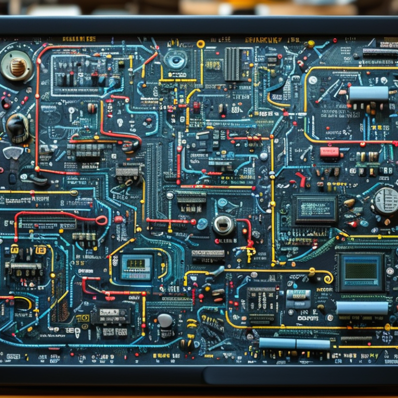
| 1. Trace the power path first | AC input and primary power supply | Fuse, switch, varistor, bridge rectifier, electrolytic capacitor, transformer | Usually located near the AC input connector and separated from low-voltage circuitry by an isolation boundary. | Converts incoming AC into regulated DC rails for the television circuits. | Follow the path from AC Line and Neutral through protection, rectification, switching, and isolation. |
| 2. Separate primary and secondary sides | Isolated power-supply boundary | Isolation transformer, optocoupler, chassis ground, secondary ground | Look for a printed isolation line or clearance gap around the transformer and feedback components. | Transfers energy while electrically isolating hazardous mains voltage from user-accessible circuits. | Do not assume primary ground and secondary ground are electrically identical; verify the diagram markings. |
| 3. Recognize the low-voltage rails | Secondary power outputs | Regulator IC, inductor, diode, filter capacitor, test point, connector | Outputs are commonly labeled with rail names such as standby, main supply, logic supply, or panel supply. | Provides stable DC voltages for the main board, timing controller, audio circuits, and display electronics. | Check polarity, ground reference, enable signals, and the rated voltage printed beside each connector pin. |
| 4. Follow signal flow through the main board | Main processing and control board | Processor IC, memory, crystal oscillator, HDMI or video connector, transistor, voltage regulator | It connects external input ports to the display, audio, power, and user-control circuits. | Processes video and audio, manages startup, and exchanges control data with other boards. | Read arrows and connector labels from input source to processor, then toward the display and audio outputs. |
| 5. Identify the display data path | Timing controller and panel interface | Flat-flex connector, differential data pairs, clock line, buffer IC, panel power filter | The timing-controller section is positioned between the main board and the LCD panel, often using a wide ribbon cable. | Converts processed video data into synchronized row and column information for the panel. | Distinguish power pins from high-speed data pairs; the diagram may identify differential pairs by positive and negative labels. |
| 6. Read the backlight driver separately | LED backlight power and control | LED symbol, boost inductor, switching MOSFET, rectifier diode, current-sense resistor, PWM input | Located near a connector labeled for LED output, dimming, brightness control, or backlight enable. | Raises and regulates voltage for LED strings while controlling brightness and protecting against overcurrent. | Look for feedback from the LED string and a control line such as enable or pulse-width dimming. |
| 7. Use reference designators and test points | Component-level troubleshooting | R = resistor, C = capacitor, D = diode, Q = transistor, L = inductor, F = fuse, TP = test point, CN = connector | Each component has a unique reference number, while nets and connectors often carry functional labels. | Links the schematic to the physical board and helps locate components, signal paths, and measurement points. | Compare the component symbol, reference number, polarity marking, and expected measurement before replacing a part. |