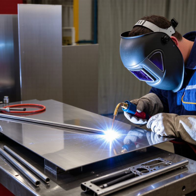
| 1. Material Preparation and Welding Setup |
| Material identification | Base material | Austenitic stainless steel 304 or 304L; verify the material certificate and heat number before welding. | Confirm grade, thickness, surface condition, and traceability. Keep carbon-steel tools and grinding dust away from the stainless-steel work area. | Prevents wrong-material fabrication and embedded ferrous contamination that can cause surface rust. |
| Joint preparation | Fit-up and joint cleanliness | Remove oil, paint, moisture, oxide, and adhesive residue. For butt joints, use a consistent root gap and avoid excessive mismatch. | Check with a calibrated ruler, feeler gauge, or welding fit-up gauge. Degrease with a residue-free solvent and allow the joint to dry fully. | Reduces porosity, lack of fusion, inclusions, and unstable arc behavior. |
| Heat control | Preheat and interpass temperature | Preheat is normally not required for clean 304/304L. Keep the interpass temperature typically below 150 °C unless the approved welding procedure specifies otherwise. | Measure with temperature-indicating crayons, contact thermometers, or calibrated infrared equipment. Record the maximum interpass temperature. | Limits distortion, excessive oxidation, and unnecessary heat exposure. |
| Shielding gas | Gas type and flow | GTAW: high-purity argon, commonly 8–12 L/min. GMAW: argon-rich stainless-steel shielding gas, commonly 12–20 L/min. Adjust for torch, nozzle, and local drafts. | Check regulator, hoses, connections, gas purity, and flow at the torch. Protect the weld area from wind and strong air movement. | Maintains an oxygen-free arc zone and reduces porosity and heat tint. |
| Filler selection | Filler metal | Use a filler compatible with the approved welding procedure, commonly ER308L for 304/304L joints. Use a low-carbon grade when corrosion resistance and sensitization control are important. | Verify filler classification, diameter, batch identification, and storage condition before use. | Supports corrosion resistance and suitable weld-metal chemistry. |
| Welding technique | Arc and travel control | Use a short, stable arc; avoid excessive weaving; maintain consistent travel speed and torch angle. Deposit stringer beads where practical. | Monitor voltage, current, wire-feed speed, travel speed, polarity, and shielding-gas coverage against the qualified welding procedure. | Controls penetration, bead shape, distortion, and total heat input. |
| 2. Common Weld Defects in 304 Stainless Steel |
| Defect prevention | Porosity | Typical causes: moisture, oil, leaks, insufficient shielding gas, excessive gas flow, drafts, or contaminated filler metal. | Perform visual inspection and use radiographic or ultrasonic testing when required by the project specification. Repair only under an approved procedure. | Gas cavities reduce weld soundness and may create leakage paths. |
| Defect prevention | Lack of fusion or incomplete penetration | Typical causes: low heat input, excessive travel speed, poor joint preparation, incorrect torch angle, or inadequate root access. | Inspect bead profile and root condition. Use penetrant, radiographic, or ultrasonic testing according to joint design and governing code. | Unfused regions reduce structural continuity and may retain corrosive contaminants. |
| Defect prevention | Crater cracking | Fill the crater before extinguishing the arc; use a controlled downslope or backstep technique where suitable. | Visually inspect weld stops and starts. Use penetrant testing when surface-breaking cracking must be ruled out. | Weld craters can shrink and crack if they are left unfilled. |
| Defect prevention | Excessive heat tint | Dark blue, purple, or black oxidation indicates inadequate shielding or excessive heat exposure. Minimize heat input and provide back purging for open-root joints when required. | Inspect both weld and heat-affected surfaces. Do not use color alone as the acceptance criterion; apply the project specification. | Heavy oxidation can reduce the corrosion performance of the stainless-steel surface. |
| Defect prevention | Tungsten or metallic inclusions | Avoid touching the tungsten electrode to the weld pool. Remove contaminated tungsten, regrind it, and maintain correct electrode extension. | Use visual inspection and radiographic testing where internal inclusions are critical. | Inclusions interrupt weld continuity and may become corrosion initiation sites. |
| 3. Post-Weld Cleaning and Surface Restoration |
| Initial cleaning | Slag, spatter, and residue removal | Remove spatter and residues using dedicated stainless-steel brushes, non-contaminating abrasives, or approved mechanical methods. | Tools used on carbon steel must not be reused on stainless steel. Clean until no visible residue remains. | Prevents iron contamination, staining, and localized corrosion. |
| Chemical cleaning | Pickling or passivation | Use a qualified commercial process selected for the weld condition and surface finish. Pickling products may contain hazardous acids, including hydrofluoric acid, and require strict safety controls. | Follow the chemical supplier's safety data sheet, contact time, temperature, ventilation, PPE, neutralization, and waste-disposal requirements. | Removes heat tint and restores a cleaner chromium-rich surface. |
| Rinsing and drying | Final surface condition | Rinse thoroughly with clean water after chemical treatment and dry without leaving chloride-rich or acidic residues. | Inspect under suitable lighting for remaining discoloration, etching, residue, water marks, or embedded particles. | Residual chemicals can cause staining and premature localized corrosion. |
| 4. Quality Inspection and Acceptance Records |
| Visual testing (VT) | Surface and profile | Check weld size, continuity, profile, undercut, overlap, arc strikes, cracks, visible porosity, spatter, and surface contamination. | Use adequate lighting and calibrated gauges. Acceptance limits must come from the applicable drawing, welding code, or project specification. | Detects many surface defects before additional testing or service. |
| Liquid penetrant testing (PT) | Surface-breaking discontinuities | Suitable for non-porous stainless-steel surfaces after cleaning and drying. Apply penetrant, dwell, remove, apply developer, and interpret indications according to the written procedure. | Use qualified personnel, controlled dwell times, and documented inspection results. Cracks and relevant linear indications are generally unacceptable unless the governing specification states otherwise. | Finds surface-breaking cracks, laps, and porosity not reliably visible to the eye. |
| Radiographic or ultrasonic testing | Internal weld integrity | Select RT or UT when internal fusion, penetration, or volumetric quality is critical and the joint geometry is suitable for the method. | Apply the examination extent and acceptance criteria specified by the governing code or contract documents. | Evaluates internal discontinuities that cannot be confirmed by visual inspection alone. |
| Dimensional inspection | Distortion and alignment | Measure final dimensions, flatness, squareness, joint alignment, and weld size against the approved drawing and tolerance requirements. | Use calibrated measuring equipment and record results before final release. | Confirms that welding has not moved the assembly outside functional tolerances. |
| Documentation | Traceability and release | Retain the approved welding procedure, welder qualification, material certificates, filler records, inspection reports, repair records, and cleaning details. | Review records for completeness, inspector authorization, equipment calibration, and closure of nonconformities. | Provides objective evidence that fabrication and inspection requirements were followed. |