| 1. Plate inspection | Steel plate is checked before forming, with material identification and dimensional checks. | Grade, thickness, width, surface condition, and material test documentation are checked against the purchase specification. | Confirms that the starting material is suitable for the specified pipe design and traceability requirements. |
| 2. Edge preparation | Plate edges are milled or otherwise prepared to create the required weld groove and fit-up. | Bevel geometry, edge straightness, plate width, and cleanliness are controlled to the applicable procedure. | Consistent edges support accurate forming and sound longitudinal welds. |
| 3. Plate forming | The plate is shaped into a cylindrical or near-cylindrical pipe shell using a forming method such as UOE or JCOE. | Forming sequence, shell geometry, roundness, and edge alignment are monitored against the required dimensions. | Controlled forming helps achieve the specified diameter and fit-up for welding. |
| 4. Tack welding and fit-up | The formed shell edges are aligned and temporarily joined before the main longitudinal weld. | Root opening, mismatch, alignment, and tack-weld condition are checked in accordance with the approved welding procedure. | Good fit-up reduces weld defects and helps maintain pipe shape during welding. |
| 5. Longitudinal SAW | The longitudinal seam is welded, commonly using submerged arc welding (SAW) on the inside and outside of the pipe. | Welding parameters, consumables, operator qualifications, and procedure records are controlled as required by the applicable specification. | A controlled welding process supports consistent seam quality through the pipe wall. |
| 6. Weld and dimensional inspection | The weld seam and pipe dimensions are inspected after welding and, where required, after mechanical expansion. | Inspection may include visual examination and specified non-destructive testing, such as ultrasonic testing or radiographic testing; the extent depends on the order and governing standard. | Inspection verifies compliance with the project’s weld-quality and dimensional requirements. |
| 7. Hydrostatic testing | The pipe is pressure-tested when required by the applicable product specification or purchase order. | Test pressure, hold time, and acceptance criteria are determined by the governing standard, pipe dimensions, grade, and order requirements. | Provides a specified check of pipe-body integrity under the test conditions. |
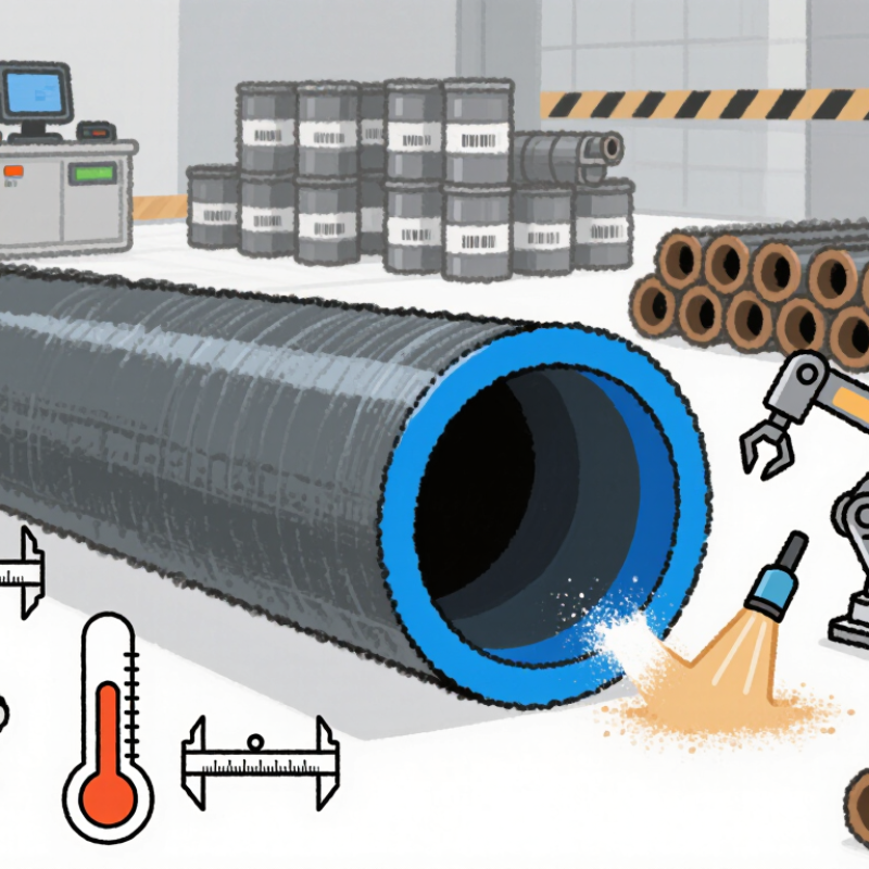
| 8. Surface preparation for FBE | The pipe surface is cleaned and abrasive-blasted before coating; dust and surface contaminants are removed. | A commonly specified cleanliness level is Sa 2½ under ISO 8501-1. A profile in the approximate range of 50–100 μm may be specified, depending on the coating system and project requirements. | Cleanliness and surface profile affect FBE adhesion and coating performance. |
| 9. FBE application and curing | The prepared pipe is heated, electrostatically coated with fusion-bonded epoxy powder, and cured under controlled conditions. | Pipe temperature, powder application, cure conditions, and coating thickness are controlled to the approved coating specification. Single-layer FBE thickness is project-dependent; values around 300–500 μm are commonly specified for some systems. | Correct application and curing create a continuous protective coating bonded to the steel surface. |
| 10. Coating inspection and dispatch | The finished coating is inspected, pipe ends are protected as specified, and product records are prepared for shipment. | Checks may include visual condition, thickness, adhesion, and holiday detection where required. Acceptance limits and inspection frequency follow the project specification. | Final checks help confirm coating continuity, documentation, and protection during handling and transport. |