Why Choose an Iron Pipe Bending Machine?
Why Choose an Iron Pipe Bending Machine?
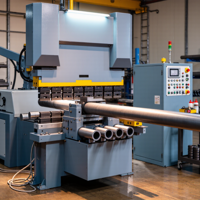
An Iron Pipe Bending Machine can turn demanding fabrication work into a more controlled, repeatable process. In practical workshops, it helps produce smooth bends for handrails, frames, supports, and industrial piping. The machine applies measured force around a selected die, reducing the uneven curves often created by manual methods. A consistent bend also saves material, especially when steel pipe is expensive or difficult to replace.
Accuracy matters.
A suitable machine improves production efficiency while protecting the pipe’s profile. Operators can reduce flattening, surface damage, and unnecessary welding adjustments. However, performance depends on the pipe grade, wall thickness, outside diameter, and bend radius. Choosing equipment without checking these details is a common mistake. It may create attractive results on one project and poor results on another.
Reliable manufacturers provide load ratings, tooling data, operating guidance, and maintenance instructions. Experienced users still verify those claims against actual workshop conditions. They inspect dies, lubrication points, electrical systems, and emergency controls before production begins. Proper training remains essential, even with automated equipment. A machine cannot correct careless setup.
The strongest reason to choose an Iron Pipe Bending Machine is dependable control, not impressive speed alone. It can support cleaner work, lower rework, and safer handling when used correctly. Yet no machine is perfect. Some jobs still require manual fitting, special tooling, or outside engineering advice. A thoughtful buyer compares long-term reliability, service support, and total operating cost before making a decision.
Iron Pipe Properties: ASTM A53 Grade B Offers 240 MPa Minimum Yield Strength
Why Choose an Iron Pipe Bending Machine?
Iron Pipe Properties: ASTM A53 Grade B Offers 240 MPa Minimum Yield Strength
ASTM A53 Grade B pipe has a minimum yield strength of 240 MPa. This value matters during bending. It indicates when permanent deformation begins under controlled testing. The pipe also has a specified tensile strength, but yield strength better guides forming decisions. A qualified technician should confirm the material certificate before selecting tooling.
A suitable pipe bending machine applies force gradually and evenly. This helps reduce flattening, wrinkles, and surface damage. Wall thickness, outside diameter, bend radius, and seam position all affect the result. A tighter radius may require a mandrel or additional support. Good machines allow controlled speed and repeatable pressure.
In practice, the first bend is rarely perfect. That deserves attention. A trial section can reveal unexpected springback or ovality before production begins. Operators should measure the bend with calipers, templates, and visual inspection. Calibration records also improve reliability. ASTM A53 Grade B is strong, yet strength alone does not guarantee easy forming. Temperature, tooling clearance, and operator experience remain important. A careful setup protects the pipe’s shape and helps maintain consistent joints during installation.
Bending Geometry: Control D/t Ratio, Centerline Radius, and Bend Angle
An iron pipe bending machine earns its value through controlled bending geometry, not raw force. In practice, the D/t ratio is a key starting point. It compares the pipe’s outside diameter with its wall thickness. A low D/t ratio creates greater risk of flattening, wrinkling, and wall thinning. Small errors matter.
An experienced operator checks the centerline radius before setting the machine. A tight CLR may suit compact layouts, but it demands better tooling and support. A larger CLR usually reduces deformation and forming stress. Mandrels, pressure dies, and proper lubrication can help maintain the round profile. I have seen a bend look acceptable while its inner wall showed unexpected wrinkles. Visual inspection alone is insufficient.
Bend angle requires equal attention. The programmed angle is not always the final angle because metal springs back after forming. A trial bend, measured with an angle gauge, can reveal the required overbend. Material grade, temperature, tooling wear, and batch differences may change the result. Measure twice. Record the actual angle and wall condition. It is tempting to rely on previous settings, but that habit can create repeatable mistakes. A dependable process combines machine control, dimensional checks, and documented inspection. The best setting is not merely fast; it protects geometry throughout the bend.
Why Choose an Iron Pipe Bending Machine? - Bending Geometry: Control D/t Ratio, Centerline Radius, and Bend Angle
Pipe Outside Diameter
(mm) | Wall Thickness
(mm) | D/t Ratio | Centerline Radius
(CLR, mm) | CLR/OD Ratio | Bend Angle
(°) | Approx. Bend Arc
(mm) | Geometry Interpretation |
| 25.0 | 2.0 | 12.50 | 50.0 | 2.00 | 90 | 78.5 | Moderate D/t with a relatively tight bend; tooling accuracy and material support are important. |
| 38.1 | 2.0 | 19.05 | 76.2 | 2.00 | 90 | 119.7 | Higher D/t indicates a thinner relative wall and greater sensitivity to ovality and wrinkling. |
| 50.8 | 3.0 | 16.93 | 101.6 | 2.00 | 45 | 79.8 | A smaller bend angle reduces arc length and may simplify dimensional inspection and positioning. |
| 76.2 | 4.0 | 19.05 | 152.4 | 2.00 | 90 | 239.4 | A larger CLR/OD ratio creates a gentler bend with generally lower forming severity. |
| 101.6 | 5.0 | 20.32 | 203.2 | 2.00 | 60 | 212.4 | The high D/t ratio requires careful control of force, pressure-die support, lubrication, and bend springback. |
Calculation reference: D/t = outside diameter ÷ wall thickness; CLR/OD = centerline radius ÷ outside diameter; bend arc length = CLR × bend angle × π ÷ 180. Actual forming results depend on material grade, yield strength, tooling design, lubrication, tube support, and machine setup.
Process Accuracy: Manage Springback, Ovality, and ISO 8492 Bend-Test Results
Why Choose an Iron Pipe Bending Machine?
Process accuracy determines whether a bent pipe performs reliably in service. Springback changes the final angle after unloading, especially with high-strength iron or steel tubing. An iron pipe bending machine can compensate through stored bend-angle data, controlled pressure, and repeatable tooling. The adjustment is not perfect. Material batches still vary.
Ovality is another practical concern. Excessive flattening reduces flow area and may weaken the bend. Proper mandrel support, clamp pressure, and die alignment help preserve the circular profile. ISO 8492:2013 evaluates tube bending through defined bend conditions and checks for visible cracking or failure. It does not provide one universal ovality limit for every application. Engineers must confirm the project specification.
A useful inspection routine measures the angle, outside diameter, wall condition, and bend radius after forming. The ISO 8492 bend-test result should be recorded with material grade, tube size, tooling, and test conditions. That record improves traceability. It also exposes mistakes.
In practice, calibration matters more than impressive machine speed. A 0.5-degree error can become significant across repeated assemblies. Digital angle feedback helps, but operators should verify parts with gauges or coordinate measurement. According to ISO 1101 principles, geometric tolerances need clear datums and defined measurement methods. Without them, “accurate” remains subjective.
Why Choose an Iron Pipe Bending Machine?
Accurate pipe bending helps control springback and ovality while improving repeatability during ISO 8492 tube bend testing. The chart shows an illustrative, non-branded process-control example; actual acceptance limits depend on pipe material, diameter, wall thickness, bend radius, and the applicable product specification.
